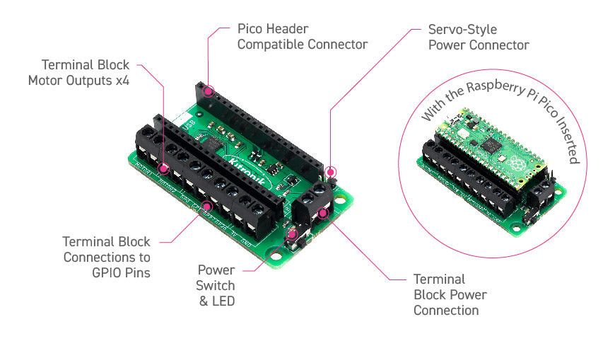
With this circuit board the Raspberry Pi Pico (attached with header pins) can control two motors simultaneously with full forward, reverse and stop control, making it ideal for Pico-controlled buggy projects. Alternatively the board can be used to drive a stepper motor. The board uses a DRV8833 motor driver IC with built-in short-circuit, over-current and thermal protection.
The board provides 4 external connections to the GPIO pins and 3V and GND power from the Pico. This allows extra IO options for your buggy builds that the Pico can read or control. There is also an on/off switch and a power status LED so you can see at a glance whether the board has power and save batteries when your project is not in use.
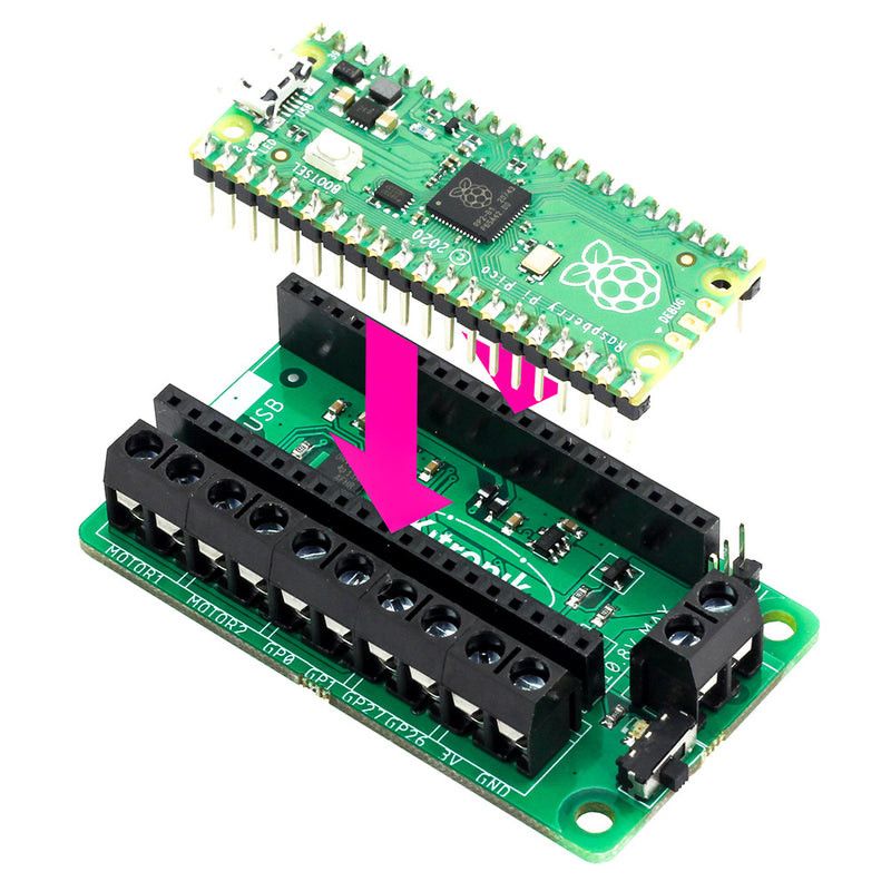
To use the motor driver board the Pico must have a soldered header and be pushed firmly into the connector. The board produces a regulated supply which is fed into the Pico via the 40-pin connector that powers the Pico, so the Pico does not need to be powered separately. The motor driver board is powered either via the screw terminal or via a servo-style connector.
Kitronik have developed a MicroPython module and example code to support using the motor driver board with the Pico. This code is available from the GitHub repository.
Features:
Small but feature rich board designed to be the heart of Raspberry Pi Pico robot projects.
The board can control 2 motors simultaneously with full forward, reverse and stop control.
It uses a DRV8833 motor driver IC with built-in short-circuit, over-current and thermal protection.
Additionally the board includes an on/off switch and a power status LED.
The board is powered via a terminal-block style connector.
The +3V and GND pins are broken out to allow powering external devices.