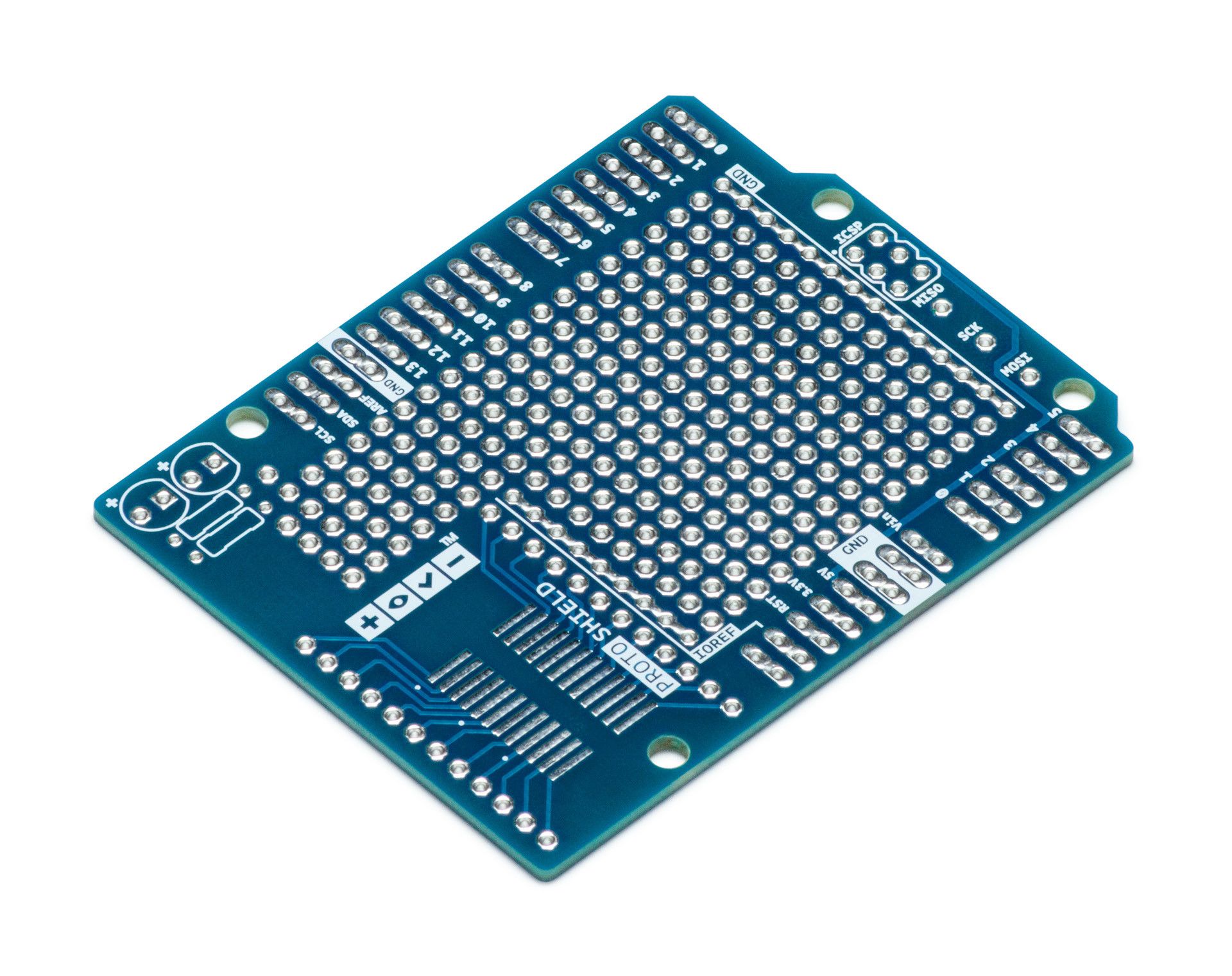
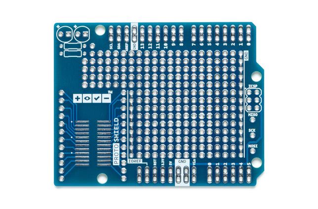
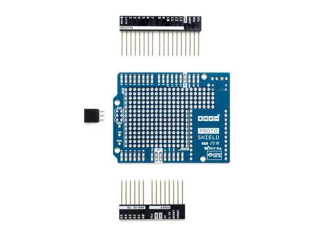
ProtoShield makes it easy for you to design your own circuits. You can easily solder TH or SMD ICs to the prototyping area and test them with your Arduino board. The SMD area is designed for up to a 24-pin SOIC integrated circuit and the TH area has plenty of room for components around your project. You can even attach a mini breadboard (not included) to the proto area for solderless use. The proto area also includes two power rails (IOREF and GND), two LED pads and breakaway pads for SPI signals for boards that have SPI only on the ICSP header, such as the Zero.
Key features
- 1.0 Arduino Pinout
- 1 ICSP connector footprint
- 2 LEDs and resistor footprint
- IOREF and GND power rails
- SPI signal pads
- 24-pin SMD footprint (50 mils pitch)
Power
The Proto Shield brings power from the Arduino-standard IOREF and GND pins to two power rails located between the plated through holes of the prototyping area, which can be used to power your project regardless of the chosen board (3V3 or 5V).
SPI connection
On the ICSP connector only 5V and GND are connected to the corresponding pins on the header. MOSI and MISO are present only on the connector and on nearby extra pads.
For more information about SPI communication see the SPI library.
Physical characteristics
The maximum length and width of the Proto Shield PCB are 2.7 and 2.1 inches respectively. Three mounting holes allow the shield to be fastened to a surface or its enclosure. Note that the distance between digital pins 7 and 8 is 160 mil (0.16"), not the same multiple of 100 mil of the other pins.
Links