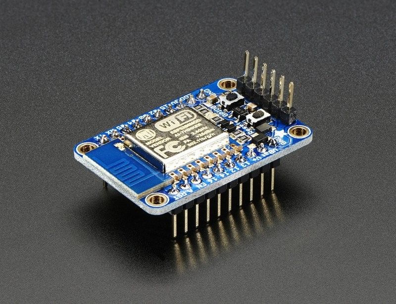
- processor: ESP8266 80MHz
- WiFi: ESP8266 WiFi module, 2.4Ghz, 802.11 b/g/n
- board regulator: 3.3V 500mA, however 250mA current consumption is recommended so the regulator does not get too hot
- GPIO: 9 pcs (SPI, I2C)
- GPIO I/O voltage: 3.3V 12mA per pin
- 1 pc analog input pin A, 1.0V maximum
- UART pins 2 pcs
- other pins: 2 pcs 3-6V power inputs, reset, enable, LDO-disable, 3.3V output, with diode protection
- reset and user button, i.e. programming button (GPIO-0), which are used to put the board into programming mode
- red LED, which is programmable
- board dimensions: 25 x 38 x 5 mm (without pin header)
- weight: 5g
- included: 36pin pin header
Programming is done with the Arduino IDE. In addition, an FTDI USB-UART programming cable 3.3V is required.
Serial control and bootloading pins (UART pins):
TX pin: 3.3V, RX pin: 5V, which has its own level shifter to 3.3V
The TX and RX pins next to the board antenna and mounting hole, and at the end, are connected to each other.
The FTDI programming cable is connected to the end (check the connector wiring).
This Partcon FTDI programming cable works and can be connected directly to the board's pin header (pinout is the same).